Buck and Boost Converters: Understanding Voltage Step-Down and Step-Up Circuits
Introduction
DC-DC Converters are among the most fundamental building blocks in modern electronics. Whether you are working on a robot, a control board, a battery charger, or any electrical project, you will often need to either step down (Buck) or step up (Boost) a voltage.
In this article, we will explore two basic circuits used in almost all power systems, explaining their mechanism, design laws, and practical simulation results.
First: The Buck Converter (Step-Down)
How a Buck Converter Works
A Buck converter steps down the input voltage to a lower output voltage while maintaining high efficiency. The essential components are:
- An electronic switch S1
- An inductor L
- A diode D1
- A capacitor C2
- A load resistor R1
Mechanism of Action
1. When S1 is ON
- The input voltage is directly applied to the inductor.
- The inductor current increases according to the relation:
- Energy is stored in a magnetic field within the inductor.
2. When S1 is OFF
- The voltage across the inductor suddenly drops.
- The inductor maintains current continuity through the diode D1.
- The energy is discharged into the load and the capacitor.
Result: The output voltage is lower than the input voltage.
Basic Mathematical Relationship
The output voltage is determined by:
Where D = Duty Cycle = the proportion of time the switch is ON.
Example: For D = 0.4 and Vin = 12V, we get
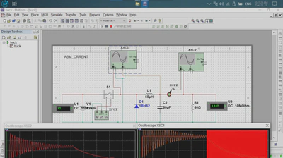
Waveform Analysis
The curve shows the natural behavior of LC circuits:
- Initial transient response
- Fluctuation of the inductor current during ON/OFF states
- Voltage stabilization over time
Second: The Boost Converter (Step-Up)
How a Boost Converter Works
A Boost converter steps up the voltage from a lower value to a higher one. The essential components are:
- A switch S2
- An inductor L1
- A diode D1
- An output capacitor C2
- A load resistor R1
Mechanism of Action
1. When S2 is ON
- The inductor is connected to the input voltage only.
- The inductor current increases, and the magnetic field is stored.
2. When S2 is OFF
- The inductor tries to maintain the current.
- The voltage rises rapidly across the diode.
- The capacitor is charged to a voltage higher than Vin.
Basic Mathematical Relationship
The output voltage follows the relation:
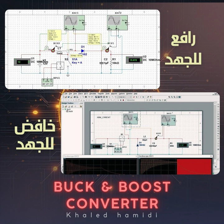
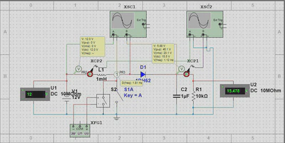
Example from the simulation: With D = 0.2 and Vin = 12V, we calculate
This is very close to the measured value: 15.478V.
Waveform Analysis
The curve shows:
- A gradual increase in voltage
- The output stabilizes at ~15.4V
- A time response that depends on the L and C values
Quick Comparison
| Circuit | Function | Basic Relationship |
|---|---|---|
| Buck | Steps down voltage | |
| Boost | Steps up voltage |
Conclusion
The Buck and Boost circuits are the foundation of voltage converters in all modern electronics. Understanding them is essential for any engineer working in fields such as:
- Robotics
- Solar power systems
- Battery chargers
- Microcontroller units
- Portable systems
Multisim software allows you to simulate these circuits and verify the correct values before implementing them in reality.
